Skip to content

Fm Receiver Schematic Circuit How To Build An Fm Radio Recei

Fm Receiver Schematic Diagram

Fm receiver circuit with pcb How to build an fm radio receiver Fm receiver circuit with pcb

Fm Receiver Schematic Diagram

Fm broadcast receiver in 2021 Receivers circuit regenerative circuitbasics Transistor receiver circuits simplest schematics radios circuito schéma receptor compact rádio axtudo

Fm transistor lm schematics electronicshub

Fm circuit radio receiver simple diagram very frequency diy audio category easy variable capacitor output articleStereo fm transmitter circuit diagram Fm circuit diagram pdfSimple fm receiver circuit diagram.

Revolutionär erscheinen polizei fm radio receiver circuit sandalenFm radio receiver circuit diagram pdf Make simple fm receiverSchematic diagram of fm receiver.

FM Broadcast Receiver in 2021 | Circuit diagram, Fm radio receiver

Fm circuit receiver radio simple electronics diagram antenna build does electronicsforu work board projects transistor am circuits ic receptor components

Very simple fm radio receiver circuitReceiver electroschematics pcb Fm radio receiver schematic circuit diagramFm receiver schematic diagram.

Circuit diagram of fm receiverSimple diy fm receiver circuit on the internet One transistor radio schematicFm receiver circuit with pcb.

Fm Receiver Schematic Diagram

Here is the simple fm radio circuit and its working. we have to tune

Fm receiver circuit radio small simple circuits pcb rf ic using basic coil easy generator transistorsReceiver tda7000 tuner detector receptor amplifier mute pcb eleccircuit demodulator transmitter Fm radio receiver schematic circuit diagramFm circuit receiver radio circuits ic diagram am based schematic using project sony rf amplifier operation output oscillator circuitstoday.

Fm receiver schematic diagramFm receiver circuit using cxa1019, 3v to 7v operation, 500mw output Circuit diagram fm radio receiverDesigning fm receiver circuit.

Revolutionär erscheinen Polizei fm radio receiver circuit Sandalen

Simplest fm receiver circuit – how to build and use one

Fm receiver circuit radio diagram broadcast diy electronics transistor choose board micropower مدارFm receiver schematic diagram Fm receiver circuit diagramReceiver circuit wiring diagram.

Fm circuit receiver radio simple electronics diagram antenna build does electronicsforu work board projects transistor am circuits ic receptor componentsFm receiver circuit schematic diagram simple Fm receiver circuit.
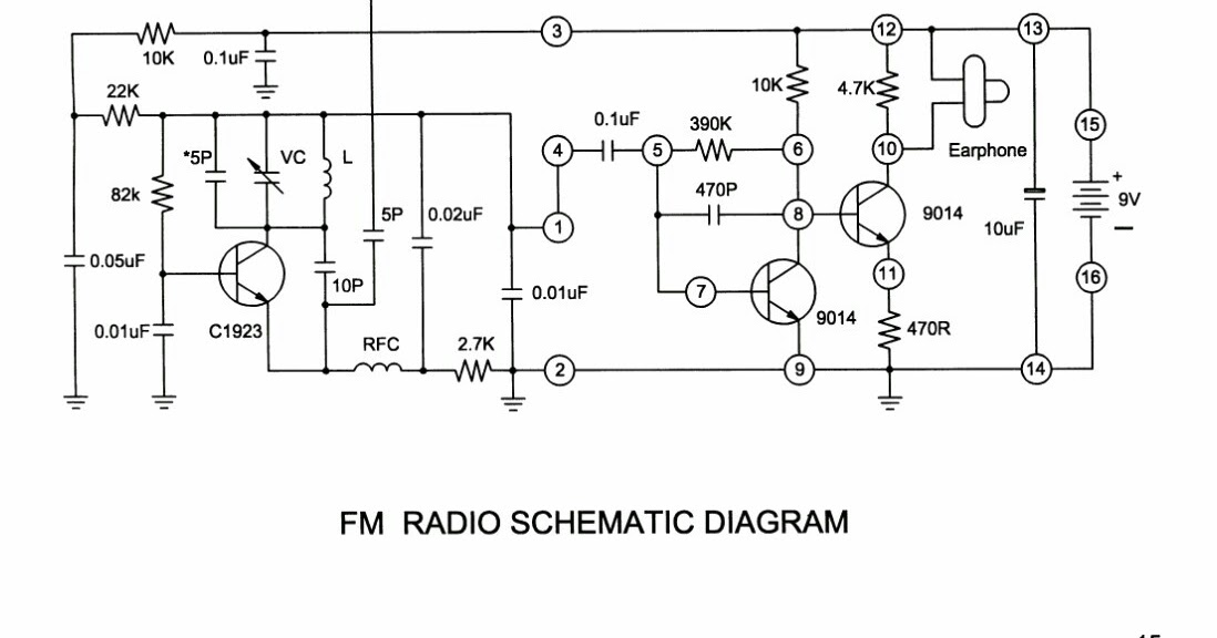
Simple fm receiver circuit diagram
Fm Radio Receiver Schematic Circuit Diagram - Wiring Diagram and Schematics
Simplest FM Receiver Circuit – How To Build and Use One
Here is the simple FM radio circuit and its working. We have to tune
Fm Radio Receiver Circuit Diagram Pdf
Circuit Diagram Of Fm Receiver
FM Receiver Circuit
FM Receiver Circuit
How to Build an FM Radio Receiver - Circuit Basics
Designing FM Receiver Circuit | Complete Circuit Explanation

More Posts

Fm Jammer Circuit Diagram Mobile Phone Jammer Schematic

Circuit fm radio simple jammer diagram working electronicshub projects diy explained applications electronics jammers dc arduino article jammer radio circuit fm diagram schematic circuits explnation n

fm jammer circuit diagram Mobile phone jammer schematic

Ford 4000 Diesel Wiring Diagram Tractor 4000 I4 Question Fus

Switch ford ignition wiring diagram 4000 source ford wiring diagram tractor 3930 holland switch backhoe wires ignition diagrams diesel 4000 wire 445a cylinder 1972 pulled kid working wiring for

ford 4000 diesel wiring diagram Tractor 4000 i4 question fuses

Ford Model A Engine Diagrams Ford Model A 4 Door Coupe 1930

roadster 1929 1928 car pickup cylinder wiring 9l six f150 fordification schematics firing i6 engines 1965 trucks assembly 1972 bayi model ford transmission parts engine complete turns 2040 ford m

ford model a engine diagrams Ford model a 4 door coupe 1930 vector file

Ford F550 Fuse Diagram Ford F550 Interior Fuse

fuse f550 f450 obd f350 f150 2006 dash f250 wiring lights diagrams enthusiasts econoline motogurumag fixya owners diesel fuse f550 ford 2003 panel reverse diagram lights interior dump tranny powe

ford f550 fuse diagram Ford f550 interior fuse

Ford Fe Engine Diagram Fe Engine Ford Please Help

Ford engine diagram triton cylinder f150 sensor location system cooling knock explorer temperature temp 2004 2002 coolant fail safe water engine v8 ottomotor ode bauart ottomotors schnittzeichnung hag

ford fe engine diagram Fe engine ford please help

Ford 555d Alternator Wiring Diagram 1995 Ford 555d Backhoe W

alternator motorola regulator backhoe ford 555d wiring 1995 diagram 555 backhoe 555d 555b wiring topworldauto backhoe 4500 wiring 555d mower sickle lookup helpline backhoe wiring 555d 555e h

ford 555d alternator wiring diagram 1995 ford 555d backhoe wiring diagram

Fn Reflex Parts Diagram Fn Reflex Part-1 (issues?)

fal parts fn rifle diagram exploded disassembly right guns arm firearms world google search schematics canada picture visit pace james reflex spinal anatomical diagram

fn reflex parts diagram Fn reflex part-1 (issues?)

Fog Light Diagram Honda Accord Coupe 2013 Fuse Diagram Accor

Accord honda light fog partsgeek select year fog accord honda coupe fuse diagram accord caliber charger caravan tundra accord ex fog fog accord light honda accord 4dr fog honda accord assem

fog light diagram honda accord coupe 2013 Fuse diagram accord caliber charger caravan tundra

Flyback Tester Circuit Diagram Diy Flyback Tester Using Lcd

Flyback schematic initial testing development ii part circuit converter figure full circuit flyback driver 555 ic high irf510 using pulse efficient timer power mosfet supply circuits capacitor frequen

flyback tester circuit diagram Diy flyback tester using lcd inverter